Flexware is basically a name
for a bunch of outback components that fit together very easily to make
your job quicker and less of a head ache. and they are right, Flexware
is pretty easy to put together. Below there are several Flexware
components:
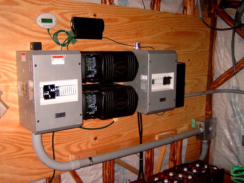
- AC distribution box (Grey box on left with breaker) part #
FW500-AC
- ACA AC conduit adapter (connector thing that connects
the AC side of the inverter to the FW500-AC box, adapter is
required!) part# ACA
- you see 2 black deals in the middle, those are the outback
inverters. part # GVFX3648 (G = grid tie, V = vented (has a fan), 36 =
3600 watt output, 48 = 48 volt system voltage - my batteries are wired
in series to get 48 volt system voltage.
- DCA DC conduit adapter (connector thing that connects
the DC side of
the inverter to the FW500-DC box, adapter is required!) part# DCA
- DC distribution box (Grey box on far right hand side with
breakers) part # FW500-DC
Note ** There is another
Flexware component that I did not use. It is called the FW-MP. The
FW-MP is basically a large metal plate that all the components easily
screw too for ease of grounding and organization. I did not use it
because it was cheaper for me to use ground lugs and all my extra wire
to bond (ground) all the devices/cans to each other. I basically
saved
myself about $150. The only issue was that it took some effort
to line
all the inverters/ adapters, and distribution boxes up when screwing to
the 1/2 inch plywood board behind it. (I use at least 1/2 plywood to
mount equipment- the
inverters are heavy). A FW-MP would have made the install easier but Id
rather save the money.
The really cool
thing about the outback inverters seen above is that when I do loose
grid power, we only
notice
a very slight flicker in our lights and thats about it. The inverters
(within
milliseconds) have switched over to battery backup without any real
notice.
The computer, tv,fridge, eveything on the backup panel stays on and
continues normally with no interuption. Its like having a giant
house UPS.
The next few components are not flexware but are required components
needed to finish the system.
- The little white oval deal (top left) is the "Mate" remote
monitor and control. This is how you configure the inverters via
several buttons and configuration screens. The way I have things set up
currently is this: I have the inverters setup for GRIDUSE mode. In this
mode I can program the inverters to disconnect and reconnect from the
grid at certain times. My Schedule is set up like this: On
weekdays the inverters disconnect from the grid at 8:00am (from this
point on we are running everything on the backup panel on battery only-
we can still use heavy load circuits on the grid tie panel but what we
do is try to only use the heavy load circuits on the grid tie panle
after 9:00 pm so we can take advantage of the off peak power rates
after 9:00 pm) . On weekdays the inverters REconnect back to the grid
at 9:00pm. Once they reconnect the inverters then recharge the
batteries. The reason they recharge the batteries is because most times
during the day the battereis get drained down past the float set point.
The cool thing is that after 9:00 pm we get off peak rates so we are
charging the batteries for less money. During the weekENDS we
disconnect from the grid at 8:00am and reconnect at 9:00p. I have the
LOW BATTERY CUTOFF set to around 45 volts. Now this is what I figured
out. Its bad to discharge the batteries down to anything under 20%. So
if my battereis ever get to around 46.63 volts then I really need to
connect back to the grid and charge the batteries. But what I
discovered is that during times when -- say the battereis are at around
48 volts which is about 50% and then my wife decides to use the garbage
disposal for a few seconds, what happens is that the batteries get
discharged down to below the LOW BATTERY CUTOFF for a very brief
second. However I have watched the voltage on the mate and the voltage
drop (meaning the brief drop from 48 to below
the low bat cutoff) never registered on the mate and the voltage just
pops right back up to 48volts as soon as my wife turns the disposal
off. But, guess what happens. The inverters detect that the
voltage dropped below the low battery cutoff and then they
automatically reconnect to the grid and start charging the batteries.
Not only are they charging the batteries during on peak rates (during
the day-costs more money) but with GRIDUSE mode, the inverters will not
disconnect from
the grid again until the next morning at 8:00am (per the GRIDUSE
schedule that was setup). So I have to wait all day and all night
until the morning rolls around at 8:00am to disconnect from the grid.
Unless of course I am home and I am watching it and decide to just
manually disconnect. Basically what I had to do was set the
LOWBATTERY CUTOFF setting so low that any brief heavy amp draw will not
accidentally set off the inverters to reconnnect back to the grid and
start charging because they think that the battereis are dead. The real
deal is that I really need to get more batteries to avoid this
situation. Funds are tight right now so I plan to continue with this
setup until I can afford to get 8 more batteries. So in short, during
the day we basically run the backup panel completely on battereis but
we still have the option to run any of our heavy load circuits that are
on the grid-tie-panel if we have to, ie-dryer, stove, water heater,
heatpump, etc. But, we try not to run these heavy loads until after
9:00pm to get off peak rates from the electric company.
The Black rectangle box
beside the Mate is called the hub-4
(the #4 = four
ports on it) Basically this is a 10-base-T ethernet hub that is used to
pass
communication between the Mate, the inverters,
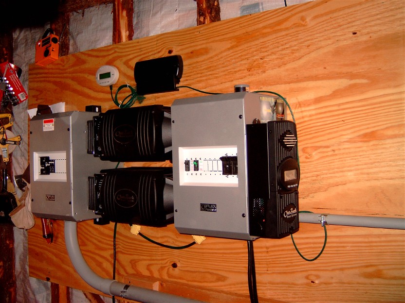
and also the MX60
charge controller (MX60 is hard to see - located on the far side of the
FW500-DC box - look at next picture to see
better shot of MX60
charge controller)
One other very important
component to this system was lightning arrestors.
On left is a square
shaped A/C
arrestor. There are two, one mounted to the top of my FW500-AC
box to protect Grid tie circuit coming in from the house and one
mounted to the bottom of the FW500-AC to protect the backup circuit
headed toward my house to the backup panel.
The DC arrestor
(round shaped) is seen in the picture (bottom right) One
is mounted to the bottom of my
FW500-dc Box to protect the master Inverter and one is mounted to the
top of the FW500-DC to protect the slave inverter.
One complaint I have about the FW500-DC and FW500-AC boxes is that
there are not enough 1/2 inch knockouts to accommodate for lightning
arrestors. If you notice, the arrestors get in the way of other
connector knockout holes. There are only two 1/2" knockouts provided :
one on the top of the FW500's and one on the bottom of
the FW500'S. Not enough in my opinion.
The A/C lightning arrestors were bought at Lowes (special order took a
few weeks to arrive) and cost about $28 each. I ended up buying about
8. They are good for two hotwires for protection on each one.The part
number is SDSA-1175 (Square-D brand). The DC arrestor was bought at
http://www.windsun.com/ for
about $29 each (Delta Brand). I bought two of these - part number is
LA-302-DC. One for the solar panel breaker
box and one at the flexware dc distribution box to protect the
batteries and MX60 charge controller..
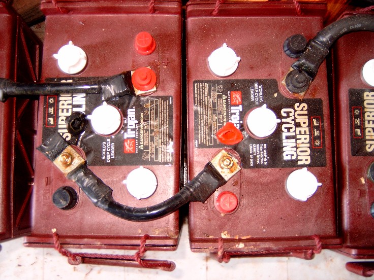
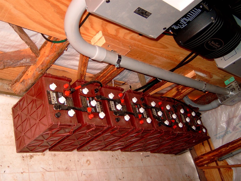
Below is a picture of the battery
bank. I used 3/0 copper THHN wire to connect the batteries in series.
As you can imagine, this wire is hard to bend. I used the crimp on type
lugs but did not have a crimper handy, so I used a large screwdriver to
beat a dent into each side of the connector to smash the connector onto
the wire. This worked just as well as a crimper but took a little extra
work. I then used electrical tape and taped up any wire that may be
showing outside of the connector. After that I used some oxide
inhibitor compound (greasy like vaseline) and smeared it all over the
battery terminial/connectors to prevent any corrosion from the hydrogen
gas that is expelled from the batteries during charging. Make sure to
cover any metal parts of the connectors that may be showing. The shack
is also intentionally not built to be very air tight and part of the
entry door is screen. This is to allow for maximum fresh air flow to
dissipate any lingering hydrogen gasses within the shack. Hydrogen gas
is of course flammable/explosive so proper venting is absolutely
required!! I may install a dc fan at some point and attach it to a
timer but
have not gotten around to that yet.
 Rockriver.us